Semantic Translation Part 2
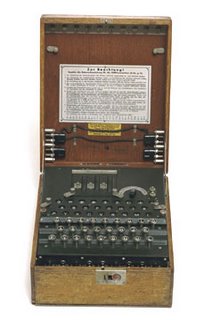
..."During World War II, the Germans used the Enigma, an electromechanical cipher machine, to develop nearly unbreakable codes for sending messages. The Enigma's settings offered 150,000,000,000,000,000,000 possible solutions, yet the Allies were eventually able to crack its code..."
It may seem like cracking a secret code when going back and forth between GIS and CAD, but luckily we have tools that make that job easier as long as we know what we're looking for.
GIS and CAD are both used to digitally store mapping data. In the CAD case often the storage of mapping features may be a secondary concern of the drawing author whose main focus is on creating a set of construction plans or generating an asbuilt survey. The language of CAD is designed to facilitate the creation and manipulation of geometry that can be used as abstract symbols of real world objects. The language of GIS is similar in that it facilitate the creation and manipulation of geometry that can be used as abstract symbols of real world objects. CAD contains many more geometric forms. GIS has the concept of data systems or spatial databases. By grouping objects together based on table of common attributes and geometric types, GIS datasets are stored as collections of features (pipes, a roads, a states, a wells...Etc). GIS symbology is derived from the feature's attributes, or identity to express a map story. CAD objects are primarily stored as symbology and their meaning is derived or assumed based on an agreed upon meaning. A red CAD line by agreement may be used to depict a road for example. Furthermore the red line may be stored on a CAD layer called road. However, there is no requirement that many different types of lines may be red or that objects that might depict other mapping feature might not also be stored on a CAD layer called road.
How data is stored, symbolized, grouped and encoded into geometric primitives in either system can be quite different. We've discussed previously that there are many standard and non-standard ways that are commonly used to encode tabular attributes, or are used to differentiate object one from another in CAD. These techniques are foreign to the GIS environment where every feature inherently has a table of attribute where information can be stored and manipulated using standard database techniques. However, CAD can still contain a wealth of "organized" information that can be made accessible to the GIS if a suitable process for interpreting and translating the data can be used.
Some of the common issues that CAD and GIS professionals face are directly related to the way data is stored in GIS and CAD. Some challenges are based on convention, relics of legacy systems, or the weaknesses or strengths of one or the other system. For whatever reason a CAD map and a GIS map may look very much the same down to the pixel on the screen or the ink mark on paper, but they can be very difficult to use together, or interchangeably in an interoperable workflow.
Here is a partial list of some of the topics we will discuss in the future that are related to successful semantic translation:
- More than one object that maps to a single object.
- A single complex object may need to be mapped to multiple objects.
- Some identifying property of one object may be inferred by inclusion, proximity, orientation or intersection with another object.
- Combinations of symbolic properties may denote physical or attribute properties.
- Cartographic license/convention may change the geometric shape of features that may need to be modified or repaired.
- Geometry may need to be simplified to be made useful in one system or another.
- Geometry may need to be enhanced or augmented to make it more useful.
- Inferred geometry may need to be added.
- Objects may hold links to external sources of information such as tables or databases.
posted by Don Kuehne at 2:24 PM
![]()
![]()


0 Comments:
Post a Comment
<< Home