October 22, 2009

ArcGIS-Ready AutoCAD Template Files

I need to compel my children to do things that are good for them, and good for the family, but they may not always see it that way. Whether it’s eating healthy or getting to sleep, or not watching TV all day, even simple things can become a battle. Routines and schedules can do a lot to help set a foundation for success. Other times I just need to set up circumstances where they can’t fail.

AutoCAD template files are most often used to pre-define layers and symbology to support my CAD standards. Using a template file with mapping specification for drawings feature layer definitions allows me to support both a CAD standard and a GIS schema at the same time. AutoCAD drawings files that contain mapping specification for drawings feature class definitions can subsequently be edited by any software that can edit the .DWG file. Because the feature layer definitions of ArcGIS for AutoCAD are stored as standard graphic and non-graphic entities in the DWG file, any software that can edit a 2007-2009 .DWG file can be a viable ArcGIS data creation tool.

Without ArcGIS for AutoCAD I would not have a way to edit any feature attributes that might also be defined as part of the feature layer. My edits would be limited to creating feature class geometry. But I can create feature class geometry in AutoCAD LT, plain AutoCAD without ArcGIS for AutoCAD loaded, or even Microstation (although I've not tired it, I would expect versions of IntelliCAD would work too). All of these can create entities in a DWG file that are recognized by ArcGIS, and ArcGIS for AutoCAD. By simply following my existing CAD standards with feature class enhanced template files, I will be populating ArcGIS feature layers no matter what tool I use. The key to my success is that the feature layer definitions are stored as filtering information on the contents of the file, what ever that ends up being.

Here is a short video of creating an AutoCAD template file that contains ArcGIS feature layer definitions...

October 13, 2009

Creating Multiple CAD files from ArcGIS

When coaching sports, executing a play can be rather complex with interrelated situational options involving both rules-based and opportunistic options that are very dynamic. Once you have diagramed the play and the team has really learned it, the result is all the players doing the right thing when the coach gives a single command. When the team doesn’t learn the play in a game there is no time to explain how each player needs to respond specifically to a given situation. Which results in the meaningless rants of coaches: “Move your feet!”, “Reverse it!”, “See the floor!”, “GO!” which taken at face value are not very instructional… but they make coaches sound wise, or at the very least make the coaches feel like they are contributing.

GIS data sets can be huge, CAD files can be big. Sometimes big gets to be too big. ArcGIS is designed to accommodate large datasets by managing data from the source in ways that it doesn’t have to load all the data into memory while also employing database science to manage large queries and analysis. The drafting environments of AutoCAD and Microstation employ high-end graphics technology that promotes fast drawing of large datasets, but was never designed for large scale data management. Traditionally the CAD solution is to break up files into vertical or horizontal tiles that can be combined together by reference or to be viewed individually. Within the context of mapping these might be vertical tiles where different drawings are stacked on top of one another based on their content discipline. For example a layer of electrical distribution data, another drawing which contains the parcel and street data, another for water, sewer etc…

Another method of tiling is by geographic zone. Horizontal tiles include all of the data in each tile, but multiple tiles are used to cover a geographic area. This form of tiling also supports the idea of pages in a map book, or districts, zones or other arbitrary or gridded system of breaking up the map. These grids may be to distribute responsibility, or they may be based on, ownership or other geographic boundaries. When moving CAD data from a gridded tiling system into ArcGIS tools like APPEND and MERGE are common tools to create a seamless map.

To recreate the tiling systems of CAD, the EXPORT TO CAD tool can be used to generate multiple files from a single GIS data set. The key is to include a field in the data sets feature attribute table called DocPath. Within this field you can populate each feature’s DocPath value to control which Microstation or AutoCAD file the data should be exported to.

First you will create a polygon grid that represents the geographic boundaries of what would be each CAD file. Then populate each polygon with a value in a field called DocPath that represents each CAD file name. Then I use that grid to perform a spatial join or an overlay function and maybe the CALCULATE tool to include the CAD DocPath on each feature I intend to export. I then invoke the EXPORT TO CAD tool. Be sure to leave the Ignore Paths In Tables option of the EXPORT TO CAD tool unchecked because this is what this option is for.


Then MOVE YOUR FEET! :)

October 09, 2009

ArcGIS for AutoCAD Query Tool

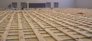
I spent last weekend installing a laminate floor in a small room off my kitchen. This was the third phase of my flooring project that has been spread out over a few years. The first being the living room, then the kitchen. In the previous two phases I pretty much did all the work myself. For this room I enjoyed the service of my capable daughter to assist me. Not only was the effort more efficient, it was also more enjoyable because I didn’t have to spend the weekend alone in the back room, doing a thousand deep knee bends… Can someone say Advil?

In a previous post I described a way to select entities based on a simple query of ArcGIS for AutoCAD feature attributes. It was really more of a simple AutoLISP code sample than a tool…

A talented colleague has created another sample query tool that I do use as my query tool for the mapping specification for drawings data used by ArcGIS for AutoCAD. If you maintain attributes in AutoCAD using the mapping specification for drawings I recomend that you download this as your query tool.

October 02, 2009

REVIT to ArcGIS

The downside of online shopping. I needed an odd sized bolt made of brass for my old sailboat and it was nowhere to be found in the local hardware stores. Easy enough to pay a little extra for shipping to save me the trouble of driving all over town. I quickly found a couple different vendors and chose the one that looked like they were really doing e-business and pushed the button and waited for the confirmation. Two phone calls and three, “ we shipped it yesterday emails”, still no bolt after over a month. Sometimes grabbing hold of the real thing and walking it to the register is the best way to go. Until e-business and boat hardware inventory systems are more interoperable… I’m off to the hardware and marine supply stores to find, and grab a 8 ½ inch quarter-twenty brass carriage bolt and matching wing nut that I can put in a bag, buy, take home and fix to my boat. …but wait I see another confirmation in my inbox.

Although, far from being an integrated system, I still have a need to get data from REVIT into ArcGIS. Here is the path I used last time I did this to create features in ArcGIS. You may find other paths to get there. Working with one DXF file exported from REVIT. The resultant AutoCAD file contained 3D entities that ArcGIS doesn’t support (Polymeshes). However, exploding them with the AutoCAD EXPLODE command did create 3D Faces that are supported by ArcGIS. From REVIT I can also export data to a 3D Studio file (.3DS). I could have used ArcGIS at this point to bring the entire 3DS file in as single 3D symbol in ArcScene or ArcGlobe, but I wanted to get the individual building parts as separate multipatch features. I imported the .3DS file into plain AutoCAD, which generates 3D face entities directly, the type of 3D CAD entities ArcGIS does support as multipatch features. The resultant AutoCAD file could then be used in ArcGIS.
Yet another option if you are confronted with AutoCAD SOLIDS entities exported from REVIT is to use the AutoCAD 3DSOUT command to export the resultant AutoCAD SOLIDS out of AutoCAD into a .3DS file and then import them back in. The result again is 3DFace entities. (If your version of AutoCAD doesn't have the 3DSOUT command, check here.)

To make the drawings even more usable I created separate muiltipatch feature classes using ArcGIS for AutoCAD for each different building part that were easily destinquished based on their AutoCAD Layer. Now when I add the data from either of the two AutoCAD files in ArcGIS I get 3D multipatch feature layers that correspond to the different building parts. I can also use the existing CAD georeferencing tools of ArcMap to position my building in geographic space, and migrate the data into a geodatabase if needed.
FREE hit counter and Internet traffic statistics from freestats.com