December 20, 2005

The Power of Context

I thought I'd share some information I got from some spam that was passed along to me by my brother-in-law a few weeks ago. It has to do with formal rules and the contextual power of our brains. Think of when you are reading a technical blog like this one or listening to a presentation and the presenter mispeaks, uses the wrong word or mentions the wrong person's name. As the audience we can make lots of simple edits to their mistakes from context. Basically replacing the mistake with a pretty good alternative. Below is an exersize in context for those familiar with the written English language. Those who are less familiar with written English may want to try the same thing in their native language based on the rules in the paragraph that follows after that.

Rreeaercshs hvae fnoud that the poewr of ctoexnt is so sotnrg taht scytnactial ruels we tnhik are itorampnt to conimucatomin may not be as ctaricil. I reebemmr an hiortiasn in Cnilooal Wilbalimursg's pninrtig oficfe siad taht selpilng was not coridnseed as iotmnprat in conlioal tiems. As you yorsluef can atsett by udernnsndtaig waht you are reiandg so far. Tihs is a gerat emxalpe of the mavloerus diegsn of our bnrais.

The rules for the above paragraph are that the words have most of the correct letters and that the first and last letter of the word are correct. The spelling of the interior portion of each word can be scrabbled in any order. So in this or other blog posts of mine if you find mistakes... ahh, you know what I mean!

The reading of a map involves a great deal of contextual interpretation. A map is designed to be read by the viewer who through context, convention and very simple rules understands its meaning. In a digital mapping system the format of the geometry, data structures and how it is stored are irrelevant to the map viewer after the map is printed. The same cannot be said about converting mapping data from CAD to GIS. The challenge for the GIS and CAD integration professional is to encode this contextual power of our brains to grasp the meaning of a CAD map into a set of rules the computer can follow using the available software tools.

Translation Tip: In ArcGIS you can use the ANGLE parameter option of the ArcGIS NEAR command to record the angle from the point you are searching to its nearest found neighbor. The recorded angle can help you determine the orientation of that point to its found neighbor, thus allowing you to discern for example if the point is above or below the neighbor. If there are no other symbolic clues this may help you find the difference between one form of CAD annotation and another; the difference between length and slope, or bearing and distance, etc.
December 16, 2005

3D GIS and CAD: GIS-Generated 3D CAD Scenes

A hot topic these days is the desire to work with all forms of data in 3D. ArcGIS supports many forms of 3D mapping data including CAD. The ArcGIS 3D viewers include ArcScene and ArcGlobe.

ArcGIS also supports the creation of 3D GIS features from 2D and 3D CAD data and the creation of 3D CAD features from 2D and 3D GIS data.

Here is a suggestion for a clever 3D use of the EXPORT TO CAD tool... Use your GIS to parametrically populate 3D scenes in AutoCAD.

ArcGIS supports the creation of AutoCAD blocks with the ArcGIS-ArcInfo EXPORT TO CAD tool from 2D or 3D ArcGIS points. Ponder for a moment the usefulness of creating 3D blocks, of houses or telephone poles or most anything in 3D. I've used this technique for over 12 years with the now discontinued ESRI ArcCAD product.

In 1993 I prepared 3D forest visualization drawings in ArcCAD using GIS tools to run a progressive aging model that included different growth rates, fallen trees based on different thinning schedules and other statistical parameters. The output of the results of the GIS analysis models were GIS points with attributes. These attributes were applied to a look-up table that generated different sizes and types of 3D blocks to represent a 3D view of a forest including fallen trees, cut trees etc...

This same technique could be applied to all different forms of visualization such as a office floor plan, hospitals, Airports, tract homes...

To create AutoCAD blocks from ArcGIS feature classes, you'll want to make sure there is a field in the output GIS points layer called 'CADType' that includes a value of "INSERT". You need to supply an AutoCAD seed file with the block definitions that you will want to reference. There also needs to be a field called 'RefName' that includes the name of the block you want to insert. You can even change of the scale of the block you want to place. You can completely change the visualization by changing the block you insert for a point or its size. By driving the 3D object creation from a smart database centric GIS toolbox you can create some interesting and useful results. I think its a pretty cool use of the tools. Try it, its fun.

December 14, 2005

Semantic Translation Part 7: Translation Models in GIS

I am the assistant coach of my 12 yr old daughter’s basketball team and yesterday we introduced a new drill for them to practice. It is called a 3-on-2 fast break drill. The exercise involves three offensive players running down court trying to score against 2 defensive players who are waiting to stop them. The beginning of the drill always looks the same... three players approaching the two players… what happens when the two groups collide is always different and interesting. Using the basic tools of passing, dribbling and shooting the players make decisions based on the type of players they are and what the defense chooses to do. These fundamental basketball tools combine to produce an output. If players organize their tools successfully the output is a successfully made basket.

Geoprocessing (GP) model tools are similar, in that they have an input and are a collection of basic tools that are organized to produce a desired output. Just like skilled and well-coached basketball players, the result of a well-constructed geoprocessing tool will be a useful and predictable output.

You ArcGIS users can download, the GP Polygon Topology Checker for CAD. I have created this geoprocessing model that will take as input a CAD file and create polygons from lines with TEXT used to identify the resultant polygons. The acceptable input is not any CAD file, but rather a CAD file where the CAD file is drawn with a network of lines that depict polygon boundaries, and has a single identifying TEXT element within the visual boarders.

A GP model tool like this one, is a collection of other GP tools, all with an input and output. GP tools combine to create models, which are in turn considered tools themselves, which can be combined in other models or scripts to create other tools and so on and so on… This model uses a collection of basic system tools. The primary tool of this model is the FEATURE TO POLYGON tool. It assembles polygons from lines and uses point or annotation type features as identifying attributes. There are a couple of sample models in the CAD Translation Sample toolbox that perform a similar operation. What makes this model different is that it compares the output polygons to the input lines to determine if there may have been linear geometry or label errors.

Desired Workflow:
  1. Build polygons from CAD lines an text.
  2. Find line geometry errors (undershoots and overshoots)
  3. Identify missing labels
  4. Identify duplicate labels
  5. Identify orphan labels
  6. Report all errors back to a copy of the original drawing.

The idea of this workflow is that the errors are not only found or repaired, but that they reported back in a CAD format so that the CAD users can view the errors make decisions about how they should be mitigated, thus improving the quality of both the CAD data and the resulting GIS data.

There are a host of tools in ArcMap that deal specifically with GIS topology, creation and management. What makes this tool different is that these are Geoprocessing tools that can be run in a script or from ArcCatalog as part of a QA/QC or automated semantic translation routine. Furthermore the results of the analysis don’t modify the GIS data, but rather push the data back to CAD for modification there.

The model is documented with help and with descriptive ModelBuilder labels. The basic logic is as follows: The user selects and input CAD file that was drawn with a structure for which this tool was designed. The boundary lines and label text are queried from all the other content of the drawing and are used to create polygons. The original lines are then compared to the resultant GIS polygon boundaries. Using a very small BUFFER of the original lines and a tool called ERASE, the buffered lines are used as a stencil or stamp to compare against the original CAD lines. All of the geometry common to both is removed, the difference remains. That data is then output to the CAD file as potential errors. The resultant polygons will have the attributes of the labels that were found within the inferred boundaries. A comparison of all the input labels can be made with the newly formed polygons using IDENTITY. Creating a FREQUENCY report of those original labels compared to the new polygons can be used to find polygons that have more than one label point. Likewise those points that are not found within any polygon are evident. Lastly a direct query of the resultant polygons can determine those polygons that had no label point.

All of this model's queries and processes result in GIS feature classes that can then be exported back into a CAD format. Using the ArcGIS-ArcInfo EXPORT TO CAD tool the entire original CAD file can be used as a seed file to which the potential geometry errors can be added. The errors will be placed on descriptively named CAD layers to help assist in the easy navigation to the potential errors by the CAD operators using their CAD application.

Continue to Part 8

December 13, 2005

Semantic translation Part 6: The Meaning of Color

Symbolic variance in CAD is the most common way to differentiate between features. The combination of color, layer, linestyle, etc..., whether documented or not, compose the major part of a CAD drawing's codified CAD standard. When these combinations of CAD symbolic properties are known they can be leveraged to identify sets of features one from another, but can also be used to populated a feature classes' attribute table. Coded attributes can be extracted using a combination of ArcGIS queries tools like MAKE FEATURE LAYER, SELECT, etc... and then database tools like CALCULATE to populate a GIS database of attributes from information codified in the CAD symbology.

The CAD color of a line may denote the material type of a pipe. The meaning of the color RED can be documented by selecting all the converted pipes in a feature class that had the CAD color of RED,and then using a database tool like CALCULATE to change the pipe's MATERIAL field to the value of "IRON".Taking this concept one step further, you can use a look-up table. The look-up table can be a simple spreadsheet or database table with all of the possible CAD colors for pipes and another field that contains the "meaning" of those colors. That table could be joined temporarily to the feature class or the values can be transferred with a permanent joining of the table, or an operation that would copy the information into the feature class attribute table using a combination of ArcGIS tools like ADDJOIN and CALCULATE.

The point I am making here is subtly different from simply identifying features. A big part of semantic translation is not only identifying different features, but also understanding as much as possible about the CAD author's intended meaning. This meaning would include as many descriptive attributes as is needed in the GIS that may be hidden in symbology in the CAD file. This hidden information is often encoded in the CAD drawing according to symbolic or cartographic convention. Sometimes information is encoded by including CAD objects near, above, below or inside another entities. TEXT above a line may describe a feature's diameter attribute while a TEXT entity below a line may identify the feature's design length. Sometimes a feature has a different attribute when another feature is present, other times the omission of a companion object can translate into yet a different descriptive attribute.

Next time we'll examine a sample ModelBuilder model that includes some creative uses of spatial analysis tools to solve a specific workflow scenario. We'll take a look at how these ModelBuilder models are constructed and show through this one example, how you might use spatial tools in the semantic translation.

Continue to Part 7...

December 12, 2005

Semantic Translation Part 5: Layers or Layers?


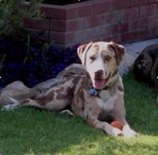
I'd like to introduce you to the newest member of my family, Sahara. She is a Catahoula Leopard Dog. She's one and a half years old and we adopted her from a dog rescue group. We anticipate that she will be a great addition to the family.

... How to spin this into a GIS and CAD interoperability example for semantic translation? ... I think the name of her breed is a good place to start. She is a "Leopard Dog" which is an oxymoron (cat/dog). It got me thinking about the similarities and differences between these two domestic carnivors and their behaviors.

Dogs and cats both have tails, but wagging them can mean something very different in one or the other. I once saw a comic strip where the care of the loving owner of both a dog and a cat invoked different responses from her pets.

The dog thinks: Hey, she feeds me, loves me, provides me with a nice warm, dry house, pets me, and takes good care of me . . .
She must be a god!

The cat thinks: Hey, she feeds me, loves me, provides me with a nice warm, dry house, pets me, and takes good care of me . . .
I must be a God!

Perhaps the conflicting jargon of GIS and CAD is worth mentioning here. The word layer within GIS can have both a general and very specific meaning. In GIS a layer is sometimes called a feature class to describe in general terms a GIS data set. Technically an ArcGIS feature layer is built from a feature class and may contain extra information about joined attributes, selection sets and symbology.

In CAD the same word layer describes a property of an entity in a drawing. Like color all entities have a layer property. Unlike the CAD color property a CAD layer property is special in that the CAD user-interface has special display behavior associated with the layer property. In CAD you can control the visibility and changeability of an entity based the CAD layer property. Technically this logical grouping and associated visibility and editing control could have been designed to use CAD color property or the linestyle property.

Unlike CAD's definition of a layer, the GIS layer has much more to do with how data is stored, identified and manipulated. The CAD layer property is transient and objects can change layers as easily as they change color. The flexibility of storing all different types of CAD entities on a single CAD layer has definite advantages in CAD. You can easily organize and manage the visibility of entities in CAD manipulating the CAD layer property.

Because GIS and CAD both use the jargon term, layer, to describe an important data organization concept there is bound to be some confusion. CAD drawings could be structured to mimic the rules of homogeneous feature type and data system consistency, but there is nothing in the CAD application that would limit the data to these arbitrary restrictions. Simply importing a CAD sewer layer will not guarantee that you will get the desired GIS sewer layer as a result, any more than importing all the green entities in a given CAD drawing might result in GIS sewer lines.

The direct-read CAD feature class of ArcGIS displays the CAD layer property as simply another attribute in the virtual feature attribute table along with the CAD color, layer, linestyle, etc... The CAD layer behaviour is perhaps most analogous to the Group Layer concept in ArcGIS.

Continue to Part 6...

December 09, 2005

Semantic Translation Part 4: CAD Direct-Read

se·man·tic
( P ) Pronunciation Key (s-mntk) also se·man·ti·cal (-t-kl)adj.
Of or relating to meaning, especially meaning in language.
Of, relating to, or according to the science of semantics.

trans·la·tion
( P ) Pronunciation Key (trns-lshn, trnz-)n.
The act or process of translating, especially from one language into another.
The state of being translated.

In this nerdy topic, being specific is necessary to communicate my meaning. We've talked about the fact that conversion or translation without special attention to meaning is only partially useful. It is good to define the problem, but solutions are more useful! In the previous post we talked about one solution to inferred spatial relationships being handled with GIS tools that have a spatial awareness and can provide usable results to questions like, "what is close to, inside or around this object?" GIS tools can be used to codify the rules for translation. In written and spoken languages we have grammar, sentence structure and figures of speech that can be defined to some extent as rules. The rules can be expressed in terms of word definitions, conjugation, word order and then loosely by phrases that form figures of speech that are arguably harder to codify. Establishing a framework for building understanding is necessary to perform the task that takes data, applies rules and creates meaning or information. The first step in this process is to understand the words of the language to be translated.

In the case of CAD to GIS conversation the GIS must understand the CAD expressions; its geometry, properties and various forms of extended attribution. Like the translation of Chinese to English, or any language from one to another, a critical first step is understanding Chinese words. There are two major schools of thought in this first process. One is to convert one language to a middle language and from that language convert to the destination language. This has its benefits in that ideally every language would just need to be converted to a single other language and likewise from one other language, (easier said than done, but still an interesting approach). This approach creates some intermediate format, like Chinese to French, and then French to English. The richer the intermediate format the more complex the initial conversion might be, but the better the translation can be overall.

The other method is to convert the base language directly into the words of the target language. This has distinct advantages, especially if you are only concerned with translating to and from your language. A direct read can help you avoid the "Chinese telephone" problem where differences in word subtleties may be compounded by orders of magnitude from language to language or just from multiple translations. For those of you who read English as a second language and especially if you are Chinese, I apologize, but this too is an example of the problems of semantic translation since the figure of speech "Chinese telephone" does have a very specific meaning to most in the United States familiar with the child's game of the same name.

A direct read of CAD data by ArcGIS is an on-the-fly conversion. ArcGIS sees CAD files as collections of ArcGIS feature classes not as CAD drawings. On the disk they are still CAD files, but ArcGIS doesn't see them that way. ArcGIS sees CAD files as collections of GIS objects that have a table of attributes. CAD files are not stored as feature classes with tables of attributes, but ArcGIS builds a view of the CAD file in memory where it applies assumptions and applies constraints to the CAD data to turn it directly into GIS data. As discussed in a previous post this GIS abstraction of the CAD data makes it directly usable by GIS tools. The reliable and predictable conversion of CAD data to GIS data is performed by the direct read capability, provides the foundation of translation. This GIS view of the CAD data can then be used as input to GIS tools and processes to codify rules-based semantic translation in the GIS language.

Continue to Part 5...

December 08, 2005

Semantic Translation Part 3: Composite Features


Combining Apples and Oranges is perhaps not necessarily the best way to characterize GIS and CAD interoperability, unless you consider that what we are really trying to do is create a GIS fruit salad. If the science of databases is applied to the problem of GIS and CAD translation one would discover that these two different databases contain various rows and columns and related tables of information. These rows and columns are generally well defined on the GIS side. On the CAD side instead of a formal database we may consider them more like collections of spatial spreadsheets or like a CSV files of geometry that have one or more different attributing schemes as discussed in a previous post. CAD may not be a database, but you can make some assumptions and create a view of a drawing as a database table. (More about that in a future post.)

One very common and straight forward method of assembling mapping features with descriptive, or identifying attributes is to place a separate TEXT entity near, inside, or on the CAD entity it is intended to describe. Instead of some foreign-key that links the two spatial database records together, there is a relationship that is inferred based combinations of proximity, inclusion, orientation or intersection. For example a TEXT entity may be placed into a CAD drawing near the midpoint of a LINE entity that itself is intended to depict a pipe feature. The TEXT entity displays the diameter of the pipe. When the drawing is read as a map document someone knowledgeable about the map's content and cartographic expressions, sees the text near the line, and by convention understands that the meaning of the combination of the blue line and accompanying text is a water pipe of a certain diameter.

Using an object-by-object conversion that includes the TEXT entities and LINE entities would result in two separate autonomous objects. There are no digital links between the two separate objects that were placed by the drawing author. The text was placed with the intention that their relationship would be assumed and understood based on its proximity to the midpoint of a line.

As luck would have it, GIS software excels at spatial analysis and relationship building. Standard GIS tools like NEAR, SPATIAL JOIN's, INTERSECT, and IDENTITY provide the means to resolve these tyes of inferred relationship. Tools that find the mid-point of lines, like FEATURE TO POINT, or or POLYGON TO LINE also provide the means to be more specific about the orientation of objects one to another. You can see some of these ArcGIS tools in being applied within the CAD Translation Sample Toolbox.

Continue to Part 4...

December 07, 2005

Semantic Translation Part 2


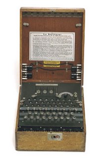
..."During World War II, the Germans used the Enigma, an electromechanical cipher machine, to develop nearly unbreakable codes for sending messages. The Enigma's settings offered 150,000,000,000,000,000,000 possible solutions, yet the Allies were eventually able to crack its code..."

It may seem like cracking a secret code when going back and forth between GIS and CAD, but luckily we have tools that make that job easier as long as we know what we're looking for.

GIS and CAD are both used to digitally store mapping data. In the CAD case often the storage of mapping features may be a secondary concern of the drawing author whose main focus is on creating a set of construction plans or generating an asbuilt survey. The language of CAD is designed to facilitate the creation and manipulation of geometry that can be used as abstract symbols of real world objects. The language of GIS is similar in that it facilitate the creation and manipulation of geometry that can be used as abstract symbols of real world objects. CAD contains many more geometric forms. GIS has the concept of data systems or spatial databases. By grouping objects together based on table of common attributes and geometric types, GIS datasets are stored as collections of features (pipes, a roads, a states, a wells...Etc). GIS symbology is derived from the feature's attributes, or identity to express a map story. CAD objects are primarily stored as symbology and their meaning is derived or assumed based on an agreed upon meaning. A red CAD line by agreement may be used to depict a road for example. Furthermore the red line may be stored on a CAD layer called road. However, there is no requirement that many different types of lines may be red or that objects that might depict other mapping feature might not also be stored on a CAD layer called road.

How data is stored, symbolized, grouped and encoded into geometric primitives in either system can be quite different. We've discussed previously that there are many standard and non-standard ways that are commonly used to encode tabular attributes, or are used to differentiate object one from another in CAD. These techniques are foreign to the GIS environment where every feature inherently has a table of attribute where information can be stored and manipulated using standard database techniques. However, CAD can still contain a wealth of "organized" information that can be made accessible to the GIS if a suitable process for interpreting and translating the data can be used.

Some of the common issues that CAD and GIS professionals face are directly related to the way data is stored in GIS and CAD. Some challenges are based on convention, relics of legacy systems, or the weaknesses or strengths of one or the other system. For whatever reason a CAD map and a GIS map may look very much the same down to the pixel on the screen or the ink mark on paper, but they can be very difficult to use together, or interchangeably in an interoperable workflow.

Here is a partial list of some of the topics we will discuss in the future that are related to successful semantic translation:


  1. More than one object that maps to a single object.
  2. A single complex object may need to be mapped to multiple objects.
  3. Some identifying property of one object may be inferred by inclusion, proximity, orientation or intersection with another object.
  4. Combinations of symbolic properties may denote physical or attribute properties.
  5. Cartographic license/convention may change the geometric shape of features that may need to be modified or repaired.
  6. Geometry may need to be simplified to be made useful in one system or another.
  7. Geometry may need to be enhanced or augmented to make it more useful.
  8. Inferred geometry may need to be added.
  9. Objects may hold links to external sources of information such as tables or databases.

Continue to Part 3...

December 06, 2005

Semantic Translation Part 1


My wife was doing some Christmas shopping for our little Guatemalan daughter, Evie, and picked up this magical animated lamp. Evie is going to love it! Upon further inspection of the packaging I discovered the perfect example to explain the benefits of Semantic Translation in GIS and CAD translation.

Look at the product name. It is classic! SEABED WORLD LAMP LIGHTING MOVE. What does that MEAN? My wife and I tried to decode it using knowledge of the product, the picture and the cryptic English word conversion. Lets pick it apart. SEABED..., an interesting choice of words. WORLD perhaps this gives us a clue to the author's intent... The product is creating an environment a WORLD. In English, I think we would say "underwater-world". LAMP..., well yes it is a lamp. LIGHTING,... Yes, it has a light and could be lighting up the room? MOVE...,well a Chinese person unfamiliar with English grammar could easily misplace the -ING ending on the verb MOVE. The words LAMP and LIGHT or LIGHTING are redundant, maybe in China the word for LAMP is not as specific as it is in English. I think what my wife bought for my daughter is a "Moving Undersea-World Lamp".

It is my opinion that GIS and CAD are likewise different spatial languages. Context, jargon, slang, word order, figures of speech and convention are all relevant to the discussion of GIS an CAD translation. Simply converting one word to another as you can see doesn't guarantee the translation is successful, or that meaning has been transferred. Here is some more text from the lamp packaging submitted for your amusement. In case you can't quite make it out, the package says:

1.) Please don't place it in the following places:
a) Nearby strong vibration.
b) in the dusty place

2.) Please do not touch in the movement.

3.) Please dno't (sp) clean it by using paint or other chemical materials. Neuter soap or cleaner as cleaning liquid is recommenable.

* This is not designed for lighting purposes, and should not be used continuously for periods over 8 hours.

4. Plesse (sp) don't place the product nearby the things that easily catch fire or curtain.

Until next post... beware of "the dusty place!"

Continue to Part 2...

December 05, 2005

Browsing for Hidden Microstation Files


My daughter had her very first basketball game this weekend. She did great, she doesn't really know all the rules yet, but she did well none the less. She even scored a basket! She is a fast learner and good athlete. I'm very proud of her. The technical distinction between traveling, pivoting and dribbling are not intuitive to her or any novice, but an understanding of them are required to perform the task of playing basketball successfully.

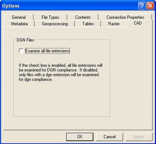
One technical rule of viewing Microstation design files in ArcGIS is that by default Microstation design files have a .DGN extension. Because of historical limitations in Microstation files sizes, the number of levels, and file naming constraints in DOS, Microstation users have taken advantage of the ability to name a file with any file extension, not just .DGN. ArcGIS by default only reads Microstation drawings with a .DGN file extension. However you can select the "view all Microstation files extensions" parameter on the CAD tab of the OPTIONS dialog box accessed from the Tool menu of ArcCatalog to alert ArcGIS to search for Microstation files with any extension.

After you do this you may still not see your Microstation files unless there is at least one CAD file in that directory with the standard CAD file extensions; .DWG, .DGN or .DXF. Having at least one standard named CAD file either real or dummy will trigger ArcGIS to scan the contents of that directory for CAD files. This is the way ArcGIS was designed to avoid scanning all files in every directory. My Suggestion is that if you have directories of Microstatoin drawings with file extensions other than .dgn, you don't have to rename them. Instead include a empty Microstation file called BLANK.dgn in the directory with your Microstation files.
FREE hit counter and Internet traffic statistics from freestats.com